What Does "Axis" Mean in a CNC Press Brake?
In a CNC press brake, an axis refers to a specific direction of movement controlled by the CNC system via servo motors. Every axis added to the machine allows the CNC controller to automate a movement that would otherwise require manual adjustment by an operator.
By controlling these mechanical components simultaneously, the CNC system ensures that the ram (the top beam) and the backgauge (the positioning system) move into the exact position required for a specific bend with micron-level repeatability.
Key Functions of Common Axis
To understand machine configurations, we must first define the roles of the individual axis:
1. Y1/Y2 (Ram Movement)
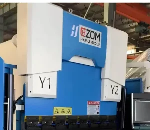
These axis control the vertical movement of the left and right cylinders of the ram. By controlling them independently, the CNC system ensures the ram remains perfectly parallel or can be tilted slightly if a specific angle correction is needed. This is the core of angle control.
2. X-Axis (Backgauge Depth)
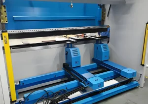
The X-aixs controls the forward and backward movement of the backgauge. This determines the “flange length” or the depth of the bend.
3. R-Axis (Backgauge Height)
This axis moves the backgauge fingers up and down. This is critical when processing parts with “down-flanges” (bends that would otherwise collide with the backgauge bar).
4. Z1/Z2 (Lateral Movement)
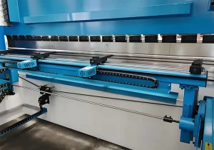
These axes move the backgauge fingers (the “points” the metal rests against) left and right. This allows the machine to automatically adapt to different workpiece widths without the operator having to stop and manually slide the fingers.
5. V-Axis (Crowning/Compensation)
While often called a compensation axis rather than a primary movement axis, the V-Axis adjusts the worktable to counteract the natural deflection (bowing) of the machine under high pressure. This ensures consistent angles across the entire length of a long workpiece.
4-Axis vs. 6-Axis vs. 8-Axis Press Brakes
| Feature | 4-Axis Press Brake | 6-Axis Press Brake | 8-Axis Press Brake |
| Typical Axis Setup | Y1, Y2, X, R (+ V) | Y1, Y2, X, R, Z1, Z2 (+ V) | Y1, Y2, X1, X2, R1, R2, Z1, Z2 (+ V) |
| Backgauge Design | · Single-unit bar · Manual finger sliding | · Single-unit bar · Automated finger spacing | Dual-independent units for total geometric freedom |
| Z-Axis (Width) | Manual adjustment required | Automated (Z1, Z2). | Automated (Z1, Z2). |
| Asymmetric Bending | · Limited · Requires manual shimming or jigs | · Difficult · Restricted by a single-bar X-axis | · Seamless · X1/X2 and R1/R2 move independently |
| Setup Time | Moderate (Manual finger positioning) | Low (Fully automated width adjustment) | Minimal (Full automation for any geometry) |
| Best For | High-volume, simple parts (boxes, brackets) | High-mix, low-volume production with varied widths | Ultra-complex, asymmetric, or non-parallel parts |
| Primary Benefit | Lowest investment cost & high reliability | Maximum efficiency for mid-range complexity | Professional-grade precision for “impossible” bends |
1. The 4-Axis Press Brake: The Versatile Workhorse
The typical configuration for a 4-axis press brake consists of the Y1, Y2, X, and R axis, and it often includes a V-axis for crowning compensation. This is the most popular configuration for small-to-medium fabrication shops because of its lower initial investment, simpler maintenance, and shorter learning curve for operators. It offers a balance of affordability and essential automation.
Best Use Cases:
- Simple rectangular parts (boxes, covers).
- Single or double-sided bends where the width of the part does not change frequently.
- Mass production of uniform parts where manual Z-axis (finger) adjustment is only required once per shift.
2. The 6-Axis Press Brake: The Efficiency Expert
A 6-axis press brake features the Y1, Y2, X, R, Z1, and Z2 axis, and it is usually equipped with a V-axis for automatic crowning compensation. The addition of independent Z1 and Z2 axes is a game-changer for shops dealing with “high-mix, low-volume” production. The 6-axis press brake significantly reduces manual labor, minimizes human error in finger positioning, and maximizes “green light” time (actual bending time).
Applications:
- Complex workpieces with varying widths across different bend steps.
- Tapered parts where the fingers must be at different horizontal positions.
- Environments where setup time (the time spent adjusting the machine between jobs) is the biggest bottleneck.
3. The 8-Axis Press Brake: The Precision Powerhouse
An 8-axis press brake incorporates the Y1, Y2, X1, X2, R1, R2, Z1, and Z2 axis, and it is almost always paired with a V-axis for high-precision crowning. In an 8-axis setup, the backgauge is split into two independent units. This means the left and right fingers can move forward/backward (X1/X2) and up/down (R1/R2) independently of one another. This model is capable of handling almost any geometry imaginable with zero manual intervention.
Ideal for:
- Non-Parallel Bends: Parts where the bend line is not parallel to the back edge of the sheet.
- Asymmetric Components: Complex parts used in aerospace, high-end medical equipment, and telecommunications.
- Extreme Geometry: Complicated odd-shaped boxes or internal tabs that require unique support positions.
Key Differences: Automation, Flexibility, and Cost
1. Level of Automation
A 4-axis machine requires the operator to be a “technician”—someone who knows how to manually set the Z-fingers correctly. An 8-axis machine turns the operator into a “loader”—the machine handles all the complex positioning, drastically reducing the risk of scrapped parts due to human error.
2. Manufacturing Flexibility
If your business model involves taking on any custom job that comes through the door, the 8-axis configuration ensures you never have to turn down a project due to technical limitations. If you specialize in standard HVAC ductwork or simple brackets, a 4-axis machine is more than sufficient.
3. Investment Cost (ROI)
The cost of a press brake increases significantly with the number of axes. Each additional axis requires high-precision servo motors, specialized drive systems, and more advanced CNC software.
- 4-Axis Press Brake offers the lowest entry cost and quickly pays for itself through steady, high-volume production of relatively simple parts.
- While it requires a higher initial investment, the 6-axis press brake often provides the fastest ROI in modern job shops by cutting setup times by up to 50% through automated finger positioning.
- The 8-axis press brake comes with the highest initial cost, but this investment is justified by the machine’s ability to produce high-value, high-margin precision parts that competitors with standard equipment simply cannot manufacture.
Selection Guide
- Quantify Your Part Complexity: Look at your 12-month production history. Do more than 20% of your parts have non-parallel bends or varying widths? If yes, look at 6-axis or above.
- Evaluate Labor Costs: In regions with high labor costs, the automation of a 6-axis or 8-axis machine is usually cheaper over a 5-year period than the cumulative hours spent by an operator manually adjusting a 4-axis backgauge.
- Precision Requirements: For aerospace or medical applications where tolerances are extremely tight, the independent control offered by an 8-axis system is often a contractual requirement.
Conclusion
Choosing the right press brake is about finding the “Sweet Spot” for your specific business:
- 4-Axis press brake is the economical choice for SMEs focused on standard parts.
- 6-Axis press brake is the gold standard for efficiency and versatility in modern job shops.
- 8-Axis press brake is the essential tool for high-end, complex, and precision-heavy manufacturing.
At CHZOM, we provide a full range of CNC press brake solutions, from 3-axis entry-level models to high-performance 8-axis synchronized systems. Our engineers are ready to analyze your technical drawings and recommend the configuration that provides the best balance of capability and cost for your specific needs.
Contact CHZOM today for a professional consultation and boost your fabrication precision.