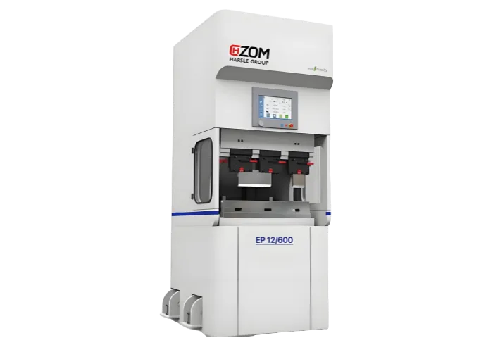
Laser cutting is the laser beam through the focus mirror into a small light projection to the metal surface, the focus to achieve a high power density, when the material is quickly heated to the vaporization temperature, evaporation to form a hole, with the beam and the material relatively linear movement, make the hole continuously formed very narrow slit, so as to achieve the purpose of cutting the material.
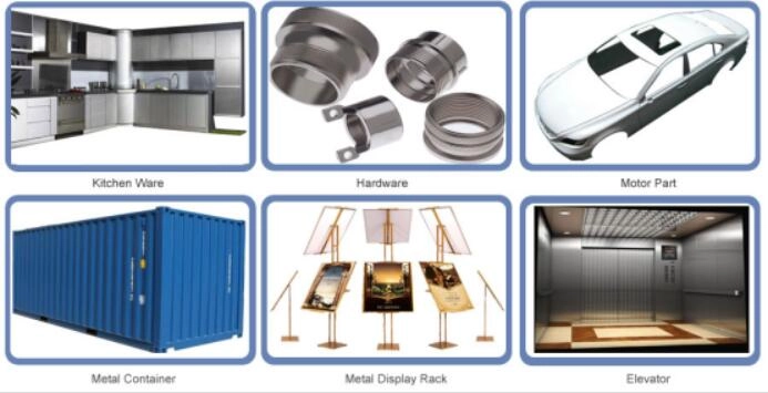
Laser cutting machine in the long-term work, the optical road will occur deviation, affect the cutting effect.Only the perfect combination of the laser tube, the reflector frame (A, B, C) and the focus mirror and the corresponding adjustment device can achieve the best results, processing the best product, which is the core part of using the laser cutter.Therefore, the regular inspection of the light road and adjustment is a very necessary work.
Components and structures
reflector mount A
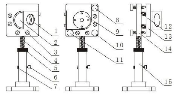
1. Light target screw 2. Mirror 3. Pull spring lock screw 4. Lock screw 3. Lock screw a7. Lock screw M1 9. Check screw M 1910.
Reflector frame B (the same as the rest of the A frame).
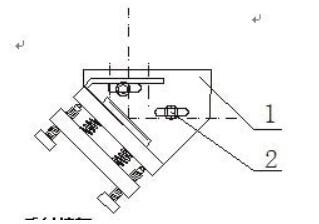
1. Install the bottom plate (which can move left to right)
2. Lock the screw
reflector mount C
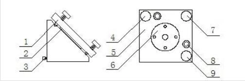
1.Mirror adjustment plate 2. Mirror 3. Lock screw 4. Adjustment screw M1 5. Mirror adjustment plate 6
Focus mirror
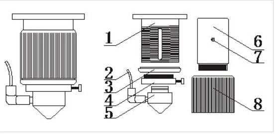
1. Focus mirror cylinder 2. intake pipe 3. Limit coil 4. Air nozzle transition set 5. Air sleeve 6.
Understanding the name of each component, let’s teach you how to adjust the laser cutter light path:
Four light road adjustment
(1) For the adjustment of the first light, stick to the dimming target hole of mirror A with beautiful paper, manually click the light (note that the power should not be used too much at this time), the base of mirror A and the laser tube support will be fine-adjusted, so that the light is hit in the center of the target hole, and note that the light can not be blocked.
(2) The second light adjustment, the mirror B to remote, with cardboard from near to far out of light, guide the light into the cross light target, because remote light must be in the target, and then the proximal and remote spot consistent, namely near how partial, remote also follow how deviation, make the cross in proximal and remote spot in the same location is near (far) the light is parallel to the Y axis rail.
(3) Adjustment of the third light (note: the cross divides the spot left and right), move the mirror C to the distance, guide the light into the light target, target once at the inlet end and the distance, and compare the position of the cross to the same as the cross in the proximal spot, which indicates that the beam is parallel to the X axis.At this time, if the light road is inside or outside, M1, M2 and M3 on frame B should be loose or tight until the left and right.
(4) For the adjustment of the fourth light, stick a piece of beautiful paper to the light outlet, make the light hole leave a circular trace on the tape, touch the light, remove the adhesive paper to observe the position of the hole, and adjust the M1, M2, M3 on the mirror frame C according to the situation until the spot is round and positive.